Personal Project · September – December 2025
UAV Optimization
Project Overview
I designed and built a custom quadcopter frame, using Computational Fluid Dynamics (CFD), Finite Element Analysis (FEA), and 3D printing to minimize frame mass while maintaining stiffness and stability.
Process Overview
Development was iterative; simulation results directly changed the frame geometry on each pass.
- Design & Simulation: ANSYS topology optimization and CFD to determine the optimal material distribution.
- Material Selection: Simulation results guided the choice of materials and manufacturing methods.
- Prototyping: Fused Deposition Modeling (FDM) for rapid prototyping of the optimized frame.
- Assembly & Testing: Internationally sourced components with in-house assembly and flight testing.
Design & Simulation
Early designs went through FEA to find stress concentrations, then topology optimization removed non-load-bearing material.
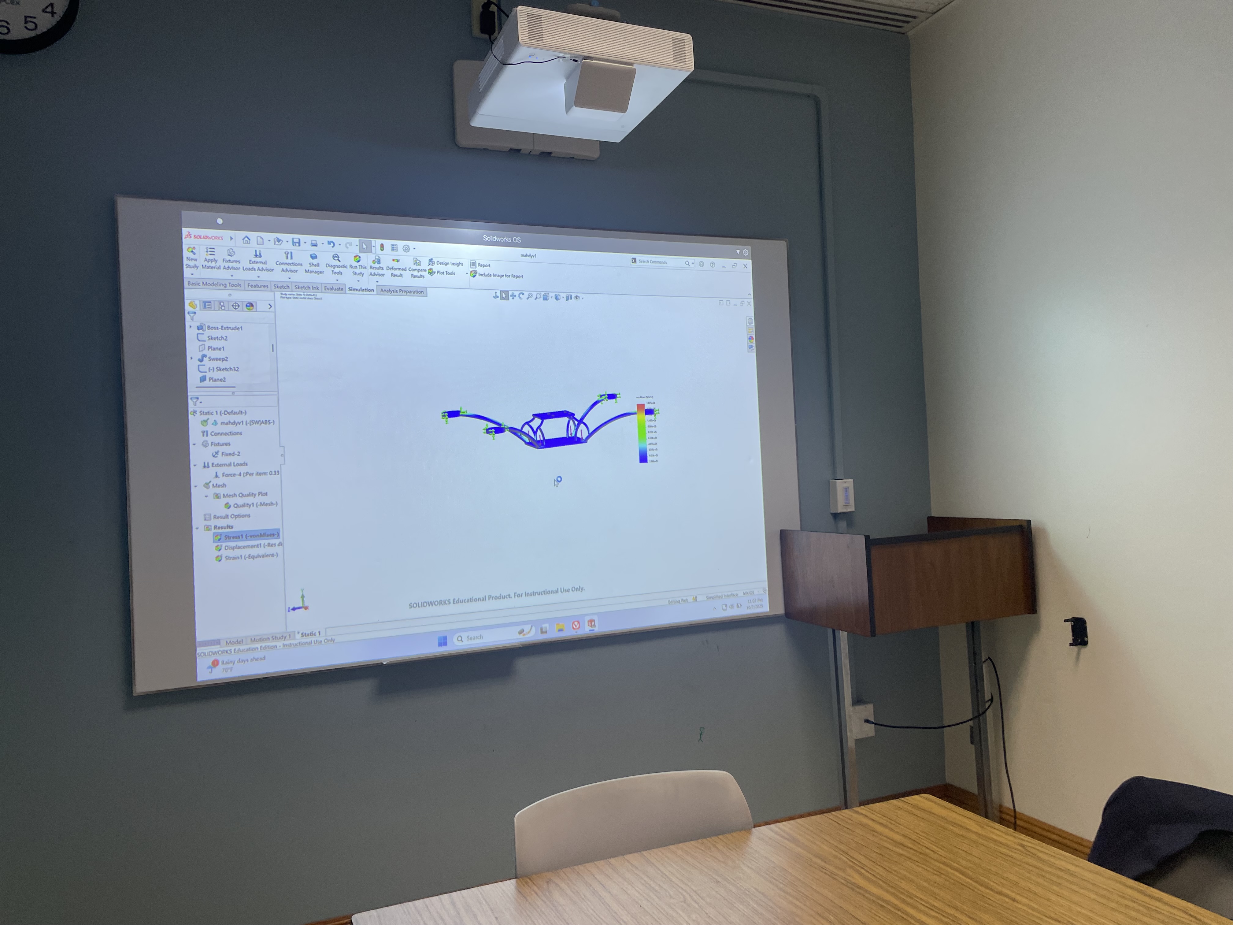
Early CAD sketches and design concepts for the drone frame.
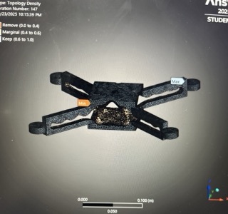
Topology optimization results showing optimal material distribution.
Fabrication & Assembly
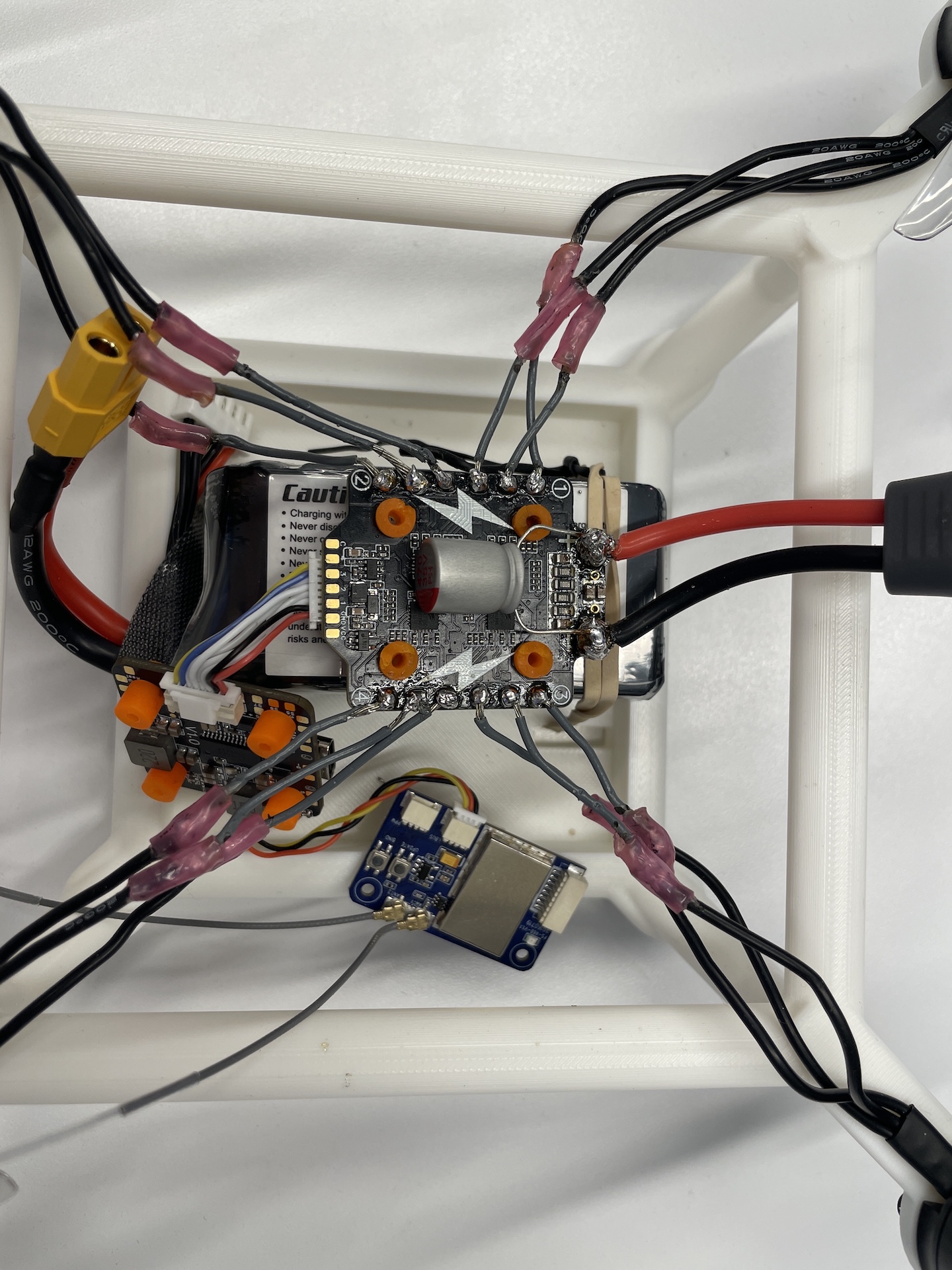
After the design passed FEA checks, I printed the frame, sourced the components, and completed the soldering and wiring.
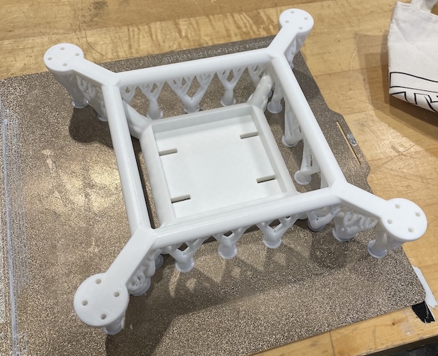
First iteration of the 3D printed frame.
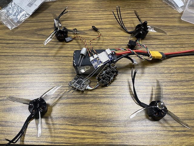
Sourced components ready for assembly.
Completed wiring and soldering of the electronic speed controllers.
Results
Topology optimization in ANSYS Mechanical cut 90% of the mass from the initial design envelope, and every overhang stayed under 45° so the frame prints without supports. FEA stress analysis confirmed a factor of safety of 2 under flight loads. Hand calculations (thrust-to-weight, inertia, stiffness) and a BOM tracked each prototype iteration.
- Mass Reduction: 90% versus the initial design envelope, with all overhangs printable below 45°.
- Structural Validation: Factor of safety of 2 under flight loads via FEA stress analysis.
- Analytical Models: Hand calculations for thrust-to-weight, inertia, and stiffness guided each iteration.
- Documentation: A detailed BOM covered sourcing and assembly.